

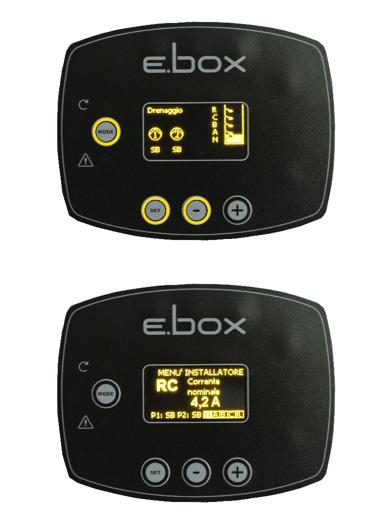
The E.Box is sold in two versions, one with display, one without display. In the display version you can enter the installer menu by pressing "mode" "set" "-" simultaneously for about 5 seconds.From this mode you can change the operating parameters. To learn more about this topic, you can register free for our online course E.Box tutorial organized by D.Training, aimed at installers, plumbers or interested people. We recommend you read the E.Box instruction manual (also available on our DNA software) for all information on the use of the product.
Was this FAQ helpful?


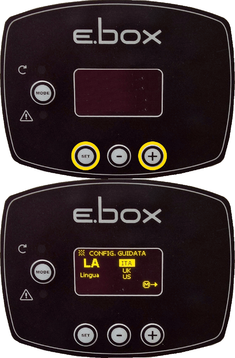
If you have the Ebox with display, there is a wizard that at the first startup guides you step-by-step of the product by requiring to the user all the necessary parameters. In this mode the device asks the user for all the parameters needed for their configuration.
If necessary, the wizard can be called by pressing simultaneously the "set" and "+" keys at power up.
To browse through wizard, use the following buttons:
• "mode" to accept the displayed parameter and go to the next
• "mode" held for more than 1 second to go back to the parameter selection
• "-" and "+" to change the value of the parameter
To learn more about this topic, you can register free for our online course E.Box tutorial organized by D.Training, aimed at installers, plumbers or interested people. We recommend you read the E.Box instruction manual (also available on our DNA software) for all information on the use of the product.
Was this FAQ helpful?


The E.Box is sold in two versions, one with display, one without display. IIn the display version errors are displayed in graphic form, in the one without display the number and color of the flashing leds indicate the type of errors. For both of them, see the following table:
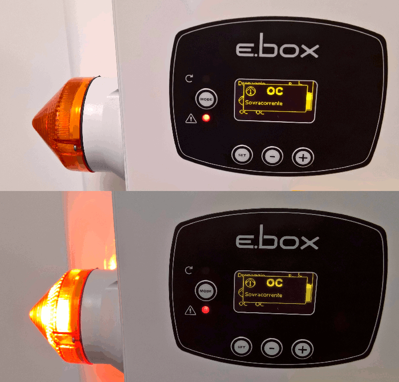
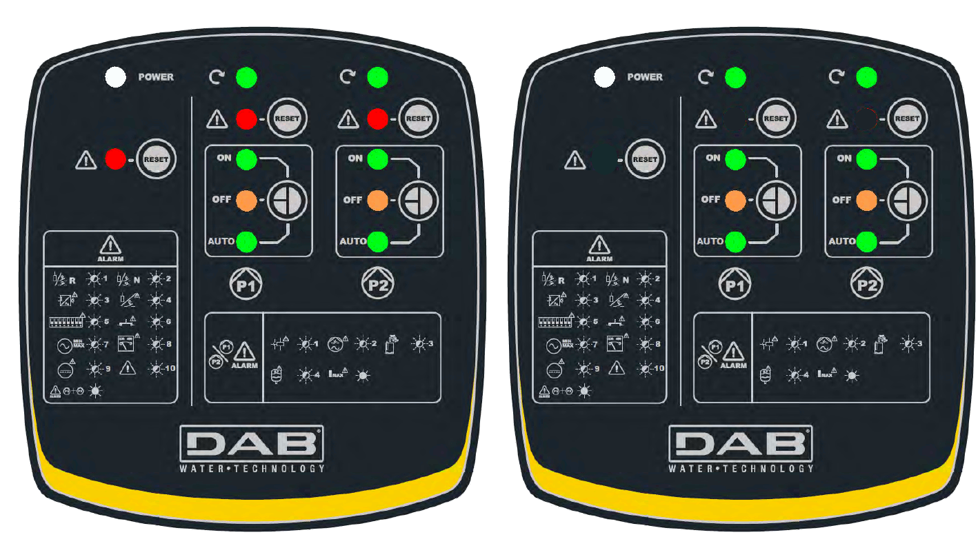
Some errors may be due to incorrect installation:
HL: Maximum level alarm
This error comes from the depth sensor, when its indication exceeds the threshold ML (Maximum Level). This can happen when the depth sensor is used for the maximum and minimum level alarms. The solution of the problem always consists of checking the set thresholds, the level of liquid in the tank and the sensor status. The panel behavior is different depending on the operative mode. In drainage this error causes the forced start of the pumps and in filling the forced stop of the pumps.
LL: Minimum level alarm
This error comes from the depth sensor, when its indication is below the threshold LOL (Minimum Level). This can happen when the depth sensor is used for the maximum and minimum level alarms. The solution of the problem always consists of checking the set thresholds, the level of liquid in the tank and the sensor status. The panel behavior is different depending on the operative mode. In filling this error causes the forced start of the pumps and in drainage the forced stop of the pumps.
BP1/BP2: Pressure sensor / depth sensor alarm
If operation with a pressure or depth sensor is selected, but the panel does not detect the sensor, the pumps are deactivated and an alarm is indicated. In this case check the wiring.
If the sensor has been correctly installed, but the sensor signal is outside the measuring range, the pumps are deactivated and an alarm is indicated. Check the pressure in the plant and, if the sensor reading is not correct, change the sensor.
FI: Floats or level probes state incoherence
This error occurs when the state of the floats or of the level probes is not correct, for example the float on the highest level of the tank indicates the presence of water and the lower floats do not. To solve these problems, check the wiring and the state of the floats. It is possible to see the position detected by the panel on the display. It is recommended to check that there are no holes in the floats.
DS: Dip Switch alarm
The Dip Switch alarm appears if the positions of the dip switches have been changed.
If the new configuration of the dip switches is valid, you are asked whether to accept it or ignore it. If it is accepted, the E.Box will start to work with the new configuration. If the new configuration is not valid, it is proposed that you ignore it.
W1: Trimmer SP
This error appears if the trimmer SP inside the panel has been moved. You are asked whether to accept or ignore the new value of SP. If it is accepted, the value of the dip switches will also be accepted.
W2: Trimmer DP
This error appears if the trimmer DP inside the panel has been moved. You are asked whether to accept or ignore the new value of DP. If it is accepted, the value of the dip switches will also be accepted.
W3: Trimmer Imax
This error appears if the trimmer Imax inside the panel has been moved. You are asked whether to accept or ignore the new value of Imax. If it is accepted, the value of the dip switches will also be accepted.
PK: Key error
If pressing of the buttons on the front board is detected in the first 30 seconds of power supply, the buttons incoherence alarm is activated. Check that the buttons function efficiently!
NL: Input voltage error
If the alternating input voltage of the panel is not within the limits established in the specifications, the input voltage alarm is given. The alarm is deactivated one minute after the alternating input voltage returns within the limits. If this error appears, check that the supply voltage is within the limits accepted by the E.Box panel, see table 1 - Technical Data.
VS: Voltage selector error
This error may occur on the E.Box plus, in the case of a fault of the E.Box Plus or breakage of the fuse FU2. In the case of an alarm, check the fuse FU2 and ensure the panel is supplied with an adequate voltage, as specified in Table 1 – Technical Data.
V0..V15: Voltage error
If the electronic board has a fault that takes one of its internal voltages to unacceptable levels, the alarm is activated for panel internal voltage error V0..V15. This error cannot be reset. The code Vx indicates the part of the circuit where the malfunction was found. If this error appears, check the supply voltages and the wiring. If everything is in order, the E.Box has suffered internal damage and must be repaired.
OM: Changed operating mode
This message is only a warning and is not an error. It appears only in the alarm log and indicates that the configuration of the E.Box has been changed, for example from drainage to pressure boosting.
E0..E15: Internal error
Panel internal error. This error cannot be reset. If this error appears, check the supply voltages and the wiring. If everything is in order, the E.Box has suffered internal damage and must be repaired.
To learn more about this topic, you can register free for our online course E.Box tutorial organized by D.Training, aimed at installers, plumbers or interested people. We recommend you read the E.Box instruction manual (also available on our DNA software) for all information on the use of the product.
Was this FAQ helpful?


2 or 3 control inputs can be used which must be connected as follows:
System with 2 floats: in this case inputs B and C are used (A must not be used). The floats in the tank must be positioned as in the figure below:
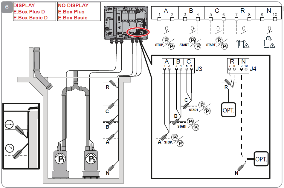
System with 2 level probes: in this case inputs B and C are used (A must not be jumpered). The level probes in the tank must be positioned as in the figure above.
System with 3 floats or level probes: in this case inputs A, B and C are used. The floats or level probes must be positioned as in the figure above. For electrical installation see:
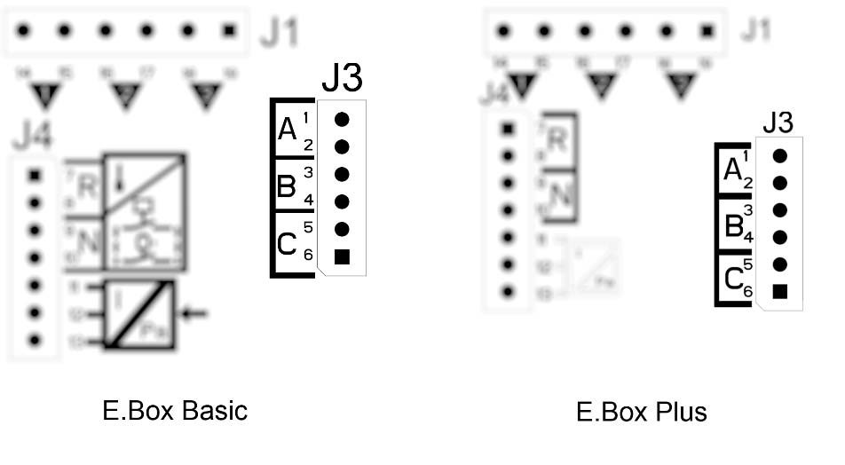
Common contact of the inputs A, B, C, R, N. There is only one common contact for all the inputs and it
is connected to the even terminals from 2 to 10. So, if electric probes are used, the common contact for
the inputs: A, B, C, R, N must be connected to the terminals with even numbers: 2, 4, 6, 8, 10.
Level probes: they can be used only with clear, clean water.
To learn more about this topic, you can register free for our online course E.Box tutorial organized by D.Training, aimed at installers, plumbers or interested people. We recommend you read the E.Box instruction manual (also available on our DNA software) for all information on the use of the product.

